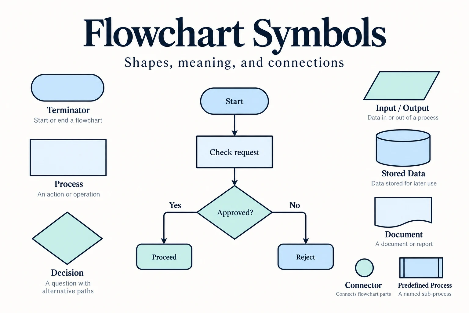
The most useful flowchart symbols are the oval or capsule for a start or end, the rectangle for an action, the diamond for a decision, and the parallelogram for input or output. Arrows show the direction of the process. Add document, storage, delay, and connector symbols when those distinctions help someone follow the work.
You can use these shapes in Mockitt's online flowchart maker to map a process before turning it into screens or a prototype. This guide explains ten common symbols, then shows how to connect them in a small order-handling example.
- The top 10 flowchart symbols and their meanings
- A worked example: handling an order
- Create and review a simple flowchart online
The Top 10 Flowchart Symbols and Their Meanings
Here are the basic flowchart symbols and their respective meanings and examples. Use the same meaning consistently throughout your diagram. A short legend helps when your team uses a less familiar symbol or a specialized notation.
1. Terminator: the start or end
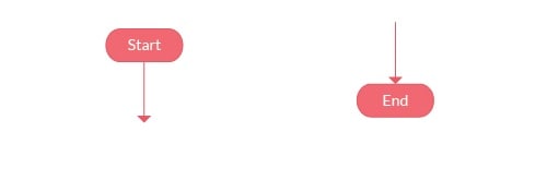
Also called the Start/End symbol, a terminator marks the beginning or end of the process being shown. Usually, the terms "Start" and "End" appear directly in the shape, which looks like a capsule. Some tools use an oval instead.
A more descriptive label, such as "Order received" or "Order ready for dispatch," tells the reader exactly where the diagram begins and ends. Explicit terminators are useful for a complete workflow, although a diagram of an intermediate subprocess may show only that part of the work. A process can also have different endings, such as fulfilled and canceled.
2. Activity/Process: an action
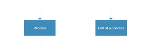
The process symbol identifies an activity or task in the flow. Its rectangle has room for an action label such as "Check stock," "Reserve items," or "Edit file."
Start the label with a verb and keep it short enough to scan. There is no fixed three- or four-word limit: "Send the order to the warehouse" is clearer than an ambiguous abbreviation. The wording inside a shape does not change its meaning; a rectangle labeled "End of a process," as in the illustration, is still a process shape. Use a terminator when you mean the workflow stops.
3. Decision: a question that changes the path
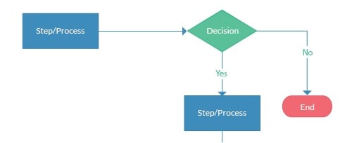
A diamond represents a decision or condition. Put a question inside it, such as "Stock available?", and label the outgoing arrows with the possible answers. "Yes" and "No" work for a binary decision; named outcomes can be clearer when there are more than two possibilities.
The diamond is not the only shape that can have multiple connections. Its purpose is to make the branching rule explicit. Every outcome that matters to the process needs a destination. A line leaving a diamond without a label forces readers to guess which condition sends them that way.
4. Delay: a waiting period
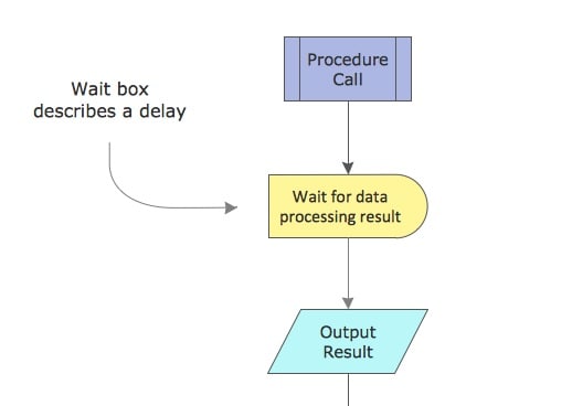
The D-shaped delay symbol shows that the process waits before continuing, for example, for a response or a scheduled event. The illustration places a wait between a procedure call and its output.
Label the waiting condition rather than writing only "Delay." "Wait for stock replenishment" explains what releases the next step. Add a duration only when the process actually specifies one. If someone is actively reviewing a request, that review is a process step; waiting for the review to begin may be a separate delay.
5. Data or I/O: information entering or leaving
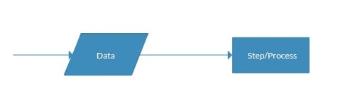
Known as the Data or Input/Output symbol, the parallelogram shows information entering or leaving the process. Examples include entering delivery details, reading a submitted form, or displaying a calculated total.
Distinguish receiving information from working on it. "Read order details" can be an input; "Calculate shipping cost" is an action and belongs in a process rectangle. This distinction makes a diagram easier to translate into system behavior.
6. Document: a readable record
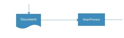
The document symbol has a rectangular outline with a wavy lower edge. It represents a document used or produced by the process, such as a report, memo, letter, invoice, or order confirmation. The arrows establish whether it is an input or an output.
Name the document, not just its file format. "Order confirmation" is more useful than "PDF." Use a process rectangle for the action "Generate confirmation" if the creation step itself needs to be shown, and a document symbol for the resulting record.
7. Database: a structured data store
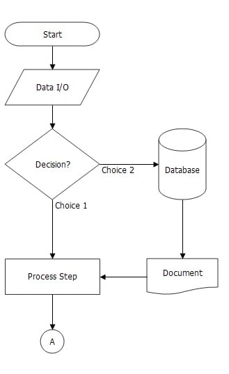
The cylindrical database symbol represents stored information that the process reads or writes. Label it with the data store's name, such as "Inventory database" or "Customer records." A database stores data about a task; it is not the task itself.
Keep actions separate when the distinction matters. "Update reserved quantity" is a process connected to the inventory database. This tells readers what changes, instead of leaving them to infer an operation from an unlabeled storage symbol.
8. Off-page connector: continue on another page
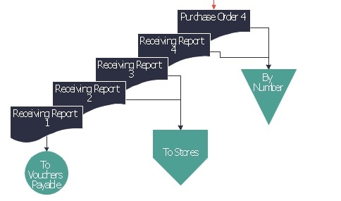
The off-page connector is often drawn as a pentagon with a downward-pointing base. It indicates that the flow continues elsewhere. In the illustration, the "To Stores" shape is the off-page connector; the other shapes serve different purposes.
Give both ends a matching reference, such as "A — Fulfillment, page 2." A page number alone can become ambiguous if the document is reorganized. Use an off-page connector when a genuine page boundary improves readability, rather than splitting a short flow unnecessarily.
9. Stored data: retained information
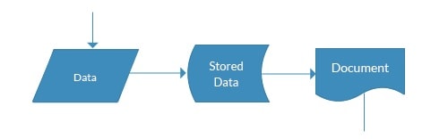
The stored-data symbol indicates information retained for later use without necessarily specifying a database or storage medium. The illustration shows data being stored before it is used in a document.
For a simple business flowchart, choose either a general stored-data symbol or a more specific database symbol according to what readers need to know. If you use both, explain the distinction in your legend. Do not switch between them for the same store merely to vary the appearance.
10. On-page connector: continue elsewhere on the same page
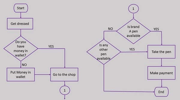
A small circle represents an on-page connector. It joins two separated sections without drawing a long line across the diagram. Put the same letter or number in both circles, as the "1" labels do in the illustration.
A connector circle is a continuation reference, not a decision or an end point. Reserve each label for one matching pair so readers can find the next step without tracing several possible destinations.
These conventions are shared by common diagramming tools, including the basic shapes described in draw.io's flowchart guide. Specialized business or technical diagrams may use additional notation. For the larger picture, see what a flowchart shows and when to use one.
A Worked Example: Handling an Order
Consider a small shop that reserves an item only after checking stock. The diagram's scope runs from receiving an order to preparing it for dispatch.
- Start: a terminator labeled "Order received."
- Input: a parallelogram labeled "Read order details."
- Action: a rectangle labeled "Check stock."
- Decision: a diamond asking "Stock available?"
- Yes route: a rectangle labeled "Reserve items," followed by an "Order confirmation" document and a terminator labeled "Ready for dispatch."
- No route: a delay labeled "Wait for replenishment," with an arrow returning to "Check stock."
The return arrow is essential: replenishment does not automatically mean the order is ready. Stock must be checked again. If the real process also permits cancellation, add that route and its own end state. You do not need to force all ten symbols into this example; introduce storage or off-page references only when they explain something the reader needs.
Create and Review a Simple Flowchart Online
Mockitt provides flowchart shapes, connectors, and a shared canvas for arranging a process. Its flowchart creation guide covers adding shapes, editing labels and styles, and sharing the result. Build the process logic first, then adjust its appearance.
Step 1. Define the process and create a flowchart
Write down the starting event and the outcome before opening the canvas. For the example above, those boundaries are "Order received" and "Ready for dispatch." Create a flowchart project in Mockitt and name it after that process. Keep shipping and returns outside this first diagram unless they are part of the question you are trying to answer.
Step 2. Add shapes, labels, and connectors
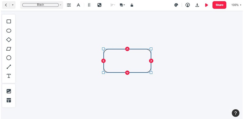
Drag the required symbols from the shape toolbar onto the canvas, then enter the action or question inside each one. Connect them in reading order and label the decision routes "Yes" and "No." The earlier Mockitt interface illustrated below shows the shape palette and the selected shape's connection points; it demonstrates the drawing controls rather than a finished process.
Keep the main route in one direction and leave room beside the decision for its alternative. Move a shape slightly after connecting it to check that the line remains attached. Use readable text and restrained colors; the meaning must still be clear without color.
Step 3. Walk through each route before sharing
Follow the example once with stock available and once with stock unavailable. The first route should reach the confirmation and end state. The second should wait and return to the stock check. A line that stops in empty space, an unanswered decision, or a connector without its matching label reveals unfinished logic.
Ask a teammate to explain the diagram without your narration. If they cannot tell what triggers a step or where a branch goes, revise the labels or connections. Share the diagram with the intended access permissions and check the shared view at its normal reading size before using it in a handoff.
Choose the Smallest Set of Symbols That Explains the Work
Start with actions, decisions, inputs, and clear boundaries. Add a document when its output matters, a delay when work genuinely waits, and a connector when it makes a large diagram easier to follow. Correct shapes help, but explicit labels and complete routes are what make the flowchart useful to the person carrying out the process.