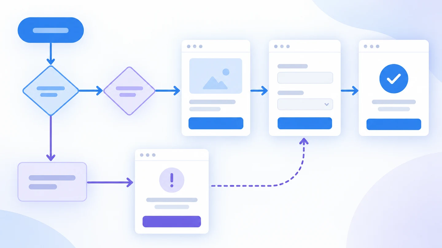
Short answer: map each user-facing flowchart node to a screen, state, or decision record before you draw the full interface. Start with the entry condition, define the action and visible result for every branch, then connect the resulting screens in an interactive prototyping workspace. This keeps the process logic and the clickable experience aligned without pretending that a prototype is a working service.
A flowchart explains what can happen. A prototype lets people inspect how that path feels and whether the interface gives them enough information to continue. Teams often lose information when they jump from a large process diagram straight to polished screens: one branch has no page, an error path returns to the wrong state, or a decision diamond is represented by a button that does not explain the consequence. A deliberate mapping pass closes that gap.
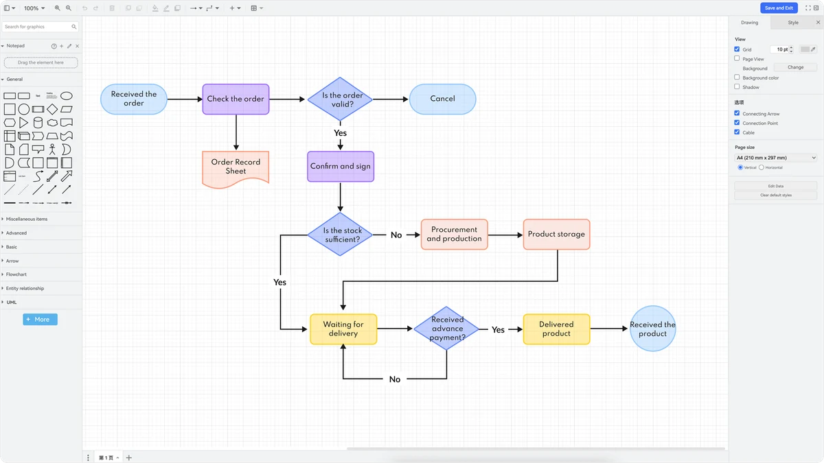
When a flowchart-to-prototype map is useful
Use the map when a task crosses several screens, roles, or outcomes. It is especially useful for onboarding, checkout, approvals, account recovery, booking, and internal operations. A simple landing page may need only a wireframe. A workflow with decisions needs a traceable relationship between the process and the interface.
The map is not a request to create one screen for every shape. A flowchart start or end node may be a condition rather than a page. A calculation may be invisible in the interface. Conversely, one node may require multiple visual states: an empty list, a loading state, a validation error, and a completed result. The purpose is to name the user-visible evidence for each meaningful step.
Step 1: Freeze the flowchart scope
Copy the smallest complete scenario into a working table. Record the actor, entry condition, expected outcome, and explicit exclusions. Do not map the whole service if the review concerns only “submit an expense” or “invite one teammate.” A narrow scope makes missing branches visible and prevents a prototype review from becoming a vague product tour.
| Flowchart detail | Record before mapping |
|---|---|
| Start node | Who starts, from which entry point, and with what information? |
| Action node | What does the user do, and what visible result should follow? |
| Decision node | Which condition is checked and what are the named outcomes? |
| End node | What does completion, cancellation, or failure mean to the user? |
| External step | What is simulated, and which real dependency remains unproven? |
Give each node a stable ID such as INV-01 or INV-02A. Stable IDs let product, design, and engineering discuss a branch without relying on changing screen names. Keep the source flowchart available as the logic reference; the prototype is the interface evidence for the selected scenario.
Step 2: Classify each node as a screen, state, rule, or dependency
Use four categories instead of assuming every node becomes a new page:
- Screen: a distinct surface that a person needs to navigate to, such as an invitation form or review page.
- State: a different response on the same surface, such as invalid input, loading, empty, success, or permission denied.
- Rule: logic that changes a visible choice or outcome but does not require its own screen, such as “only owners can submit.”
- Dependency: an external service or data condition that must be represented honestly, such as an unavailable account or a delayed response.
This classification prevents two common errors. A team may create ten almost-identical pages because it treats every state as navigation, or it may omit an error state because it assumes the happy-path screen is enough. Both make review and implementation harder.
Step 3: Build a node-to-screen matrix
Create one row for every user-visible node. Include the starting state, action, expected result, prototype destination, and evidence status. For a loan request, the matrix might look like this:
| Node | Category | Prototype evidence | Open question |
|---|---|---|---|
| LOAN-01 | Screen | Equipment choice screen with a selected item | What happens if an item becomes unavailable? |
| LOAN-02A | State | Unavailable item message with a replacement path | Can the user keep other entered information? |
| LOAN-02B | Screen | Request review with summary and edit actions | Which fields are required for confirmation? |
| LOAN-03 | State | Request sent confirmation with reference | Is the reference generated by the service? |
Mark evidence as shown, simulated, or unresolved. “Shown” means the reviewer can inspect the intended interface. “Simulated” means the prototype demonstrates a response without proving the production service. “Unresolved” means the team still needs a product or engineering decision. This vocabulary keeps a polished click path from being mistaken for a tested integration.
Step 4: Connect the primary path and the recovery paths
Connect the main scenario first, then deliberately add branches. For each transition, write the trigger and visible result in plain language: “Selecting Submit with an incomplete address shows an explanation and retains the entered value.” Avoid labels such as “go to screen 7,” which hide the behavior under review.
Walk the path in both directions where the flowchart permits it. Check back, cancel, retry, and return actions. A recovery branch should land in a state that preserves what the person needs to continue. If the diagram has a timeout or service failure, show what the user knows and what action is safe. Do not add a “Try again” control unless the responsible team has decided that a retry is safe.
Step 5: Review the map with three questions
- Coverage: does every decision outcome that changes the user task have a screen or state?
- Continuity: after each action, can a reviewer tell where the user is and what to do next?
- Truthfulness: is each external dependency labelled as simulated, pending, or verified?
Ask product to confirm scope and exclusions, design to confirm states and content, and engineering to identify assumptions that a prototype cannot prove. A flowchart-to-prototype review works best when each open item has an owner and a next decision date.
Common mapping mistakes
Mapping nouns instead of outcomes
A node named “Payment” does not tell a reviewer whether the screen is a form, a review step, a success state, or a failed authorization. Name the outcome and the evidence needed.
Ignoring data carried between nodes
When a user enters a name, amount, or selected item, show whether later screens retain it. If the prototype uses placeholder data, say so. A missing value on the confirmation screen can reveal a requirement gap before implementation.
Using one branch to stand for every branch
One happy path cannot represent permission restrictions, empty results, invalid input, and network uncertainty. Select the branches that could change the decision and model those states explicitly.
Confusing a diagram with navigation
A flowchart can contain internal rules that should never become clickable pages. Keep the rule in the matrix and expose only the user-visible consequence.
A reusable mapping worksheet
For each row, fill in: node ID; actor; starting condition; action; visible result; screen or state; next node; data carried forward; dependency; evidence status; owner; and review decision. Add a final column for “changed since last version.” That column makes it easier to review a new branch without rereading the entire prototype.
Once the worksheet is stable, use the prototype to walk the selected paths and collect comments in context. Keep the flowchart as the process source and the prototype as the interaction evidence. If the two disagree, record the decision instead of silently changing one.
Final check
A useful flowchart-to-prototype map answers three things: which process node a person is experiencing, what the interface should show, and what remains unproven. Start with a bounded scenario, classify nodes, map evidence, connect recovery paths, and review open assumptions with their owners. That sequence gives the team a clickable conversation it can test and revise, while keeping implementation decisions visible.